New Mast for Steamship Portland
Jim Spitzer
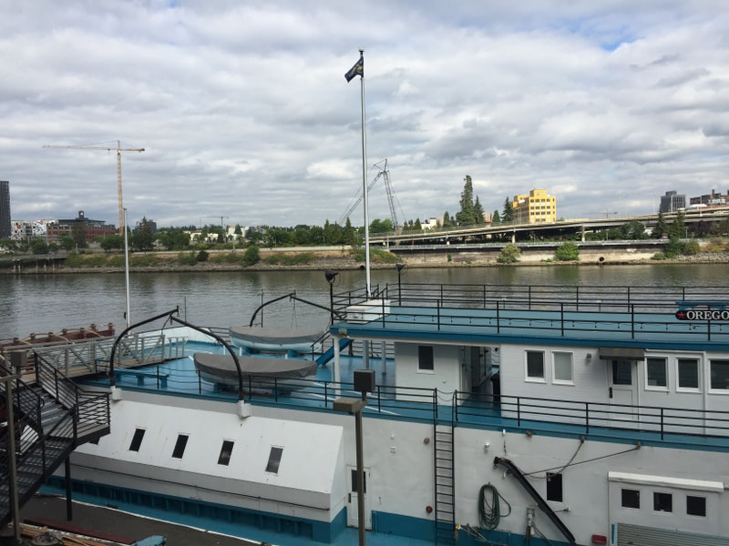
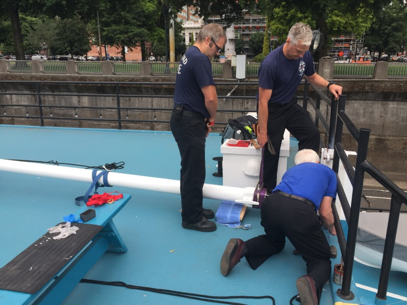
A big project at the Oregon Maritime Museum this year was the repair of the 32 foot main mast after the top couple of feet and the sheaves assembly came crashing to the deck in the Spring of 2017. There was extensive rot. With the help of Portland firefighters the mast was unstepped. Further inspection with an ice pick and moisture meter revealed rot or moisture intrusion in the upper half of the mast and at the base.
The mast never carried sail, it was for appearance (What is a ship or large boat without a mast? Unbalanced, unfinished?) and to carry navigation lights indicating the steamer was towing a vessel. The cheapest and easiest way forward was to adapt a 32 foot aluminum flagpole. But the continuous cylindrical shape and the clanging of halyards against aluminum in the wind would be wrong. Michael Neubauer, a professional Boatwright from Port Angeles, WA, was on one of our 2017 cruises. He sketched out some ideas and elaborated on mast building techniques in subsequent emails. Specifically he proposed connecting a new mast segment to the old using a swallowtail scarf joint. His wisdom gave me the confidence to proceed. Rivers West member and boat builder Ralph Cohen suggested the ultimate guide that I needed; the David Macintosh book ‘How to Build a Wooden Boat.’ Its 15 page chapter on making spars filled in the details.
So here is how I built the mast in a dozen easy steps:
|
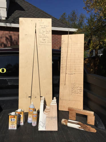
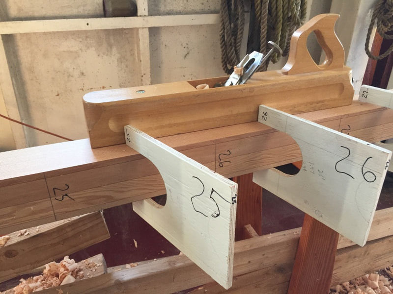
1. Design the mast and make guages
As pointed out by Neubauer, design the mast to taper with a belly. That is, don’t taper it in a straight line; keep it thicker in the mid section and taper it toward the top to the needed diameter at the top. Our mast was almost 6 inches diameter at the foot and 2 ¾” at the top where the sheaves assembly was attached. Design the taper using the design tool on the right. Horizontal lines are drawn for every foot of mast height. Mast radius of known parts are measured and marked from the centerline to the left at each known diameter at given height. In our case we knew the diameters of the lower part of the mast that we were keeping, and at the top were the sheaves assembly would be attached. Fasten a thin stick to the marks indicating the lower known radiuses, bend it to the top known radius, and draw a line along the stick. With a compass measure each radius and swing the compass to the right side of the centerline, making a mark at every foot of height. Next make gauges for each foot of height (see the stack of wood at the bottom with the first marked 32. These gauges would be frequently employed when shaping the mast to the desired thickness at each height. |
|
2. Buy Materials
The original mast was shaped from a single piece of clear, quarter sawn Douglas Fir. This was not available. I got 4 pieces of 20 foot 2x6 clear, quarter-sawn, kiln dried Fir. I picked the four best from the warehouse. About $500 wholesale! Thanks to Disdero Hardwood Wholesalers for selling at a wholesale price! While Titebond 3 wood glue would have likely sufficed, in consultation with the chemist at System Three epoxies, I decided to use their Gel Magic gap filling epoxy. This meant I would not have to apply too much clamping pressure, possibly gluing stresses into the wood that might cause the mast to bend as would was removed to taper it. Thanks to System Three and Woodcrafters for their contributions!
The original mast was shaped from a single piece of clear, quarter sawn Douglas Fir. This was not available. I got 4 pieces of 20 foot 2x6 clear, quarter-sawn, kiln dried Fir. I picked the four best from the warehouse. About $500 wholesale! Thanks to Disdero Hardwood Wholesalers for selling at a wholesale price! While Titebond 3 wood glue would have likely sufficed, in consultation with the chemist at System Three epoxies, I decided to use their Gel Magic gap filling epoxy. This meant I would not have to apply too much clamping pressure, possibly gluing stresses into the wood that might cause the mast to bend as would was removed to taper it. Thanks to System Three and Woodcrafters for their contributions!
|
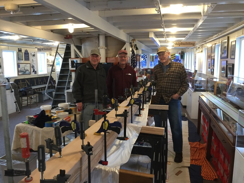
3. Glueup
The wood was stickered (space between stacked boards to allow even exposure to atmosphere) and stored in the heated cabin of the steamer for about a month. I verified that moisture readings were low and consistent and scheduled John Bouwsma, Ralph Cohen, and Chuck Stuckey to help with the glue-up. Preparations included laying out level sawhorses, borrowing about 50 clamps, lowering cabin temperature to gain more epoxy working time, and pre-measuring batches of epoxy components. Happy workers when the job was done. |
|
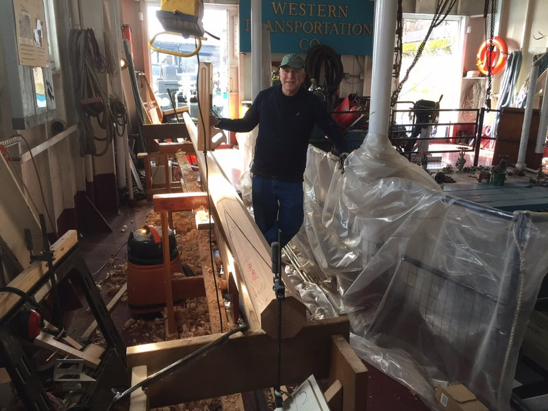
4. Work Support and Initial Measurements
The next week the glued up 20 foot long 6x6 was muscled outside, down to the barge and into the Steamer’s unheated engine room next to the boiler where it would be shaped over the next few months during my Wednesday volunteer shifts. I made a work surface of six saw horses of heights that allowed for the camber of the steamer’s main deck. They were eventually spaced to accommodate the full 32 foot length of the mast and connected together with lengths of scrap wood to be made rigid to one another. A longitudinal glue line marked the centerline of two sides, and a centerline was snapped and scribed for the other two sides. The mast height and diameter was marked for every foot on all four sides, and the diameter lines were connected.
The next week the glued up 20 foot long 6x6 was muscled outside, down to the barge and into the Steamer’s unheated engine room next to the boiler where it would be shaped over the next few months during my Wednesday volunteer shifts. I made a work surface of six saw horses of heights that allowed for the camber of the steamer’s main deck. They were eventually spaced to accommodate the full 32 foot length of the mast and connected together with lengths of scrap wood to be made rigid to one another. A longitudinal glue line marked the centerline of two sides, and a centerline was snapped and scribed for the other two sides. The mast height and diameter was marked for every foot on all four sides, and the diameter lines were connected.
|
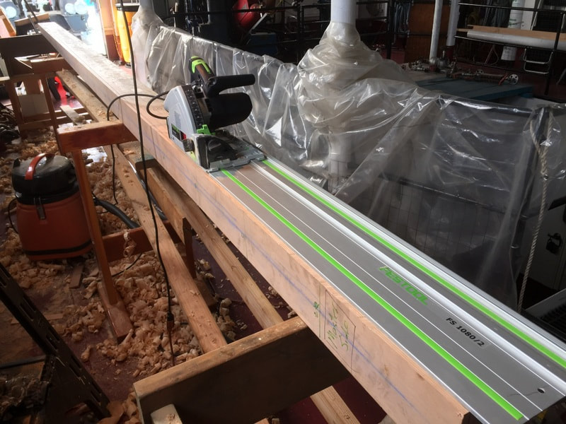
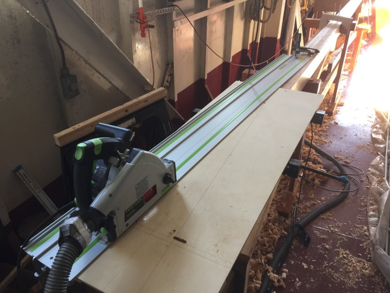
5. Initial Tapering to a Square Shape
The track saw, with blade at 90 degrees, was used to cut just outside the diameter lines on all sides. The guide was readjusted to the slowly curving diameter line for every couple of feet of cut. Center and diameter lines were often reapplied as they were cut/planed away. Many strokes of a two foot hand jointer plane and repeated use of the diameter gauges at various heights on the mast brought it into a near perfect tapered square. The saw horses were adjusted to support the now tapered mast. |
|
|
6. Cutting the Swallow Tail Scarf Joint The reinforced plywood template on the left side of the first photo was made to guide the track saw as it cut the female part of a three foot swallow tail scarf joint before starting to taper the glued-up wood. Due to the cut depth, the template/cuts were performed on opposite sides of the base of the glued upper portion of the mast. The template would be used later to cut the matching male portion of the joint on the upper part of the remaining original mast. |
|
|
7. Tapering to 8 and 16 sides Following MacIntosh’s directions, the marking gauge shown at the bottom of the first photo was made to hold pencils used to mark the lines to cut/plane to in making the square into an octagonal shape, and then to 16 sides. Each step was accomplished by working on opposite sides and frequent use of the diameter gauges while cutting or planing. |
|
|
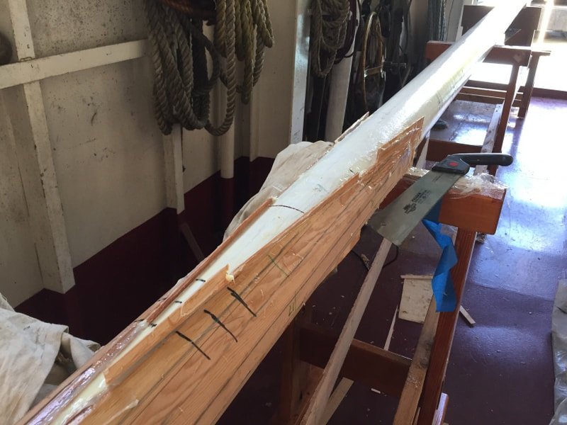
8. Swallow Tail Scarf Joint After the cutting template was used for the male part of the joint the fit was improved using hand saws, planes, and chisels. Some shims and the gap filling System Three Gel Magic did the rest. |
|
9. Taper to 32 Sides and Sanding Machine
The tapering to 32 sides was done by eye with a smoothing plane. Then MacIntosh’s sanding machine that used an inside out sanding belt powered by a power drill turning a rubber coated drum was employed to obtain a smooth cylinder shape. Additional cuts were made to accommodate the steel sleeve that slips onto the top of the mast and holds the sheave assembly.
The tapering to 32 sides was done by eye with a smoothing plane. Then MacIntosh’s sanding machine that used an inside out sanding belt powered by a power drill turning a rubber coated drum was employed to obtain a smooth cylinder shape. Additional cuts were made to accommodate the steel sleeve that slips onto the top of the mast and holds the sheave assembly.
10. Rot Prevention
In order to slow future moisture and rot problems the bottom and top of the mast and the sheave assembly were soaked in System Three S-1, a penetrating epoxy, cracks at the base were filled with epoxy paste, and the entire mast was primed and then coated with a white epoxy paint long ago donated to the Museum by Chevron Shipping Company.
11. Hardware, Sheaves, and Halyards
With the help of Portland firefighters the mast was carried up to the Texas Deck of the steamer where hardware and halyards were applied and preparations made to step the mast.
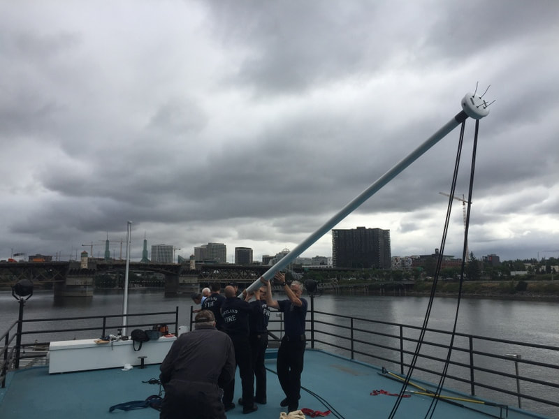
12. Stepping the Mast
Longtime steamer volunteer and Operations Chief Ron Youngman did the honors of inserting the pin through the mast and its supporting bracket while strong Portland firefighters stood it up into its proud vertical position
|
|